We are using four types of monitoring equipment at the Neda mine. First, we are monitoring the temperature and air flow in the mine itself. Secondly we have built and installed directional bat detectors. Third, we are using infra-red illuminated CCTV to monitor the entrances and calibrate the bat detectors. Lastly, we are using an Anabat unit to study the habits and identify the species found at the mine.
The bat detectors we are now using represent our second attempt at counting bat activity. Before 1999 electrical power was not available at the mine. Ed Egan and I attempted to build an bat counter that would give us a measure of the gross level of bat activity at the mine entrances.
We tried to use ultra-sonic transducers to pick up bat echo location calls as the bats were flying through the protective gratings at the entrances. We chose this method because it could be done using very little electrical power. Our goal was to be able to get a measure of bat activity and output activity pulses to a Campbell Scientific CR-10 data logger. Our plan was to use off the shelf ultrasonic transducers and low power, high gain op amp amplifiers powered by 4 "D" cells. This would have given us the ability to run the system for a couple of weeks between battery changes.
The difficulty we had was that the transducers we were able to find had a very narrow frequency response range and limited sensitivity. While we were able to detect echo location calls, we did not believe that we had any hope of translating the calls we detected into reasonably accurate bat activity numbers.
Our situation changed when electrical power was run to one of the entrances to support the research. With power in place we now had many new options. We have chosen to build custom active infra-red photoelectric beam detectors and use a CCTV (Closed Circuit Television) camera and time lapse recorder to calibrate the units.
When we began developing the bat detectors we also chose to gather directional data. To do this we use a pair of infra-red photo transistors situated so that the IR source to first one, then both and then the second is interrupted.. At this time each entry will be fitted with two sets of detectors. If you would like a copy of the detector schematic please email Herb Guenther.
![]() The bat
detector uses the circuit shown to get a directional count of bat activity.
Each set of detectors has two of the circuit modules. A resistor - diode array
is used to sum the in and out counts from each side of the detector to a single
in and out data pulse. The output is normally 5 volts DC and pulses low on bat
activity. Note that this circuit diagram is designed for those who are familiar
with electronics and does not show the power supply and power connections. If
you will need further help please feel free to email us.
The bat
detector uses the circuit shown to get a directional count of bat activity.
Each set of detectors has two of the circuit modules. A resistor - diode array
is used to sum the in and out counts from each side of the detector to a single
in and out data pulse. The output is normally 5 volts DC and pulses low on bat
activity. Note that this circuit diagram is designed for those who are familiar
with electronics and does not show the power supply and power connections. If
you will need further help please feel free to email us.
 The
Campbell Scientific data logger was counting pulses on the data wire from the
bat detector. We added this circuit to lower the input impedance of the data
wire as well as to give a local indication each time the bat detector is
tripped. The LED will blink when a bat flies through the detector. Two sets of
this circuit are used for each channel, one for in and one for out.
The
Campbell Scientific data logger was counting pulses on the data wire from the
bat detector. We added this circuit to lower the input impedance of the data
wire as well as to give a local indication each time the bat detector is
tripped. The LED will blink when a bat flies through the detector. Two sets of
this circuit are used for each channel, one for in and one for out.
![]() This is a partially assembled circuit showing the Quad NAND
gate, voltage regulator and wires leading to the infra-red emitter diode and
photo transistors. The circuits are supplied with 12 volts DC, which is reduced
to 5 volts DC by an on card regulator.
This is a partially assembled circuit showing the Quad NAND
gate, voltage regulator and wires leading to the infra-red emitter diode and
photo transistors. The circuits are supplied with 12 volts DC, which is reduced
to 5 volts DC by an on card regulator.
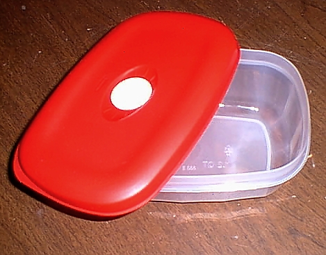 The detectors
themselves are mounted on the lid of food storage containers. The container
part is mounted to a board. The board is then mounted in the mine entries. This
is done so that the circuit is protected from moisture and damage, and can
easily be removed by snapping off the lid as illustrated below. This type of
container has a small gasketed vent in the center of the lid. We use this
gasket and hole for cable access. One side of each pair is the master. The
master has two cables, one going to the power supply and data logger, and
another cable which supplies power and receives pulses from the slave unit. The
master unit has a second circuit (not shown here) which sums the pulses and
sends them on to the data logger.
The detectors
themselves are mounted on the lid of food storage containers. The container
part is mounted to a board. The board is then mounted in the mine entries. This
is done so that the circuit is protected from moisture and damage, and can
easily be removed by snapping off the lid as illustrated below. This type of
container has a small gasketed vent in the center of the lid. We use this
gasket and hole for cable access. One side of each pair is the master. The
master has two cables, one going to the power supply and data logger, and
another cable which supplies power and receives pulses from the slave unit. The
master unit has a second circuit (not shown here) which sums the pulses and
sends them on to the data logger.
![]() This
is the "inside" view of a detector. Three 11/64th diameter holes are drilled in
the lid as shown. The photo emitter is pushed through the single hole at one
end. The two photo transistor are pushed through the holes at the other end.
Remember which photo transistor you want to be the inside one, and which is to
be on the outside. Two sets are constructed for each beam set. One side of an
entry has the emitter a the top, and the other side has it on the bottom. This
will give you two sets of detection "beams" separated by about 6 inches.
This
is the "inside" view of a detector. Three 11/64th diameter holes are drilled in
the lid as shown. The photo emitter is pushed through the single hole at one
end. The two photo transistor are pushed through the holes at the other end.
Remember which photo transistor you want to be the inside one, and which is to
be on the outside. Two sets are constructed for each beam set. One side of an
entry has the emitter a the top, and the other side has it on the bottom. This
will give you two sets of detection "beams" separated by about 6 inches.
![]() This
is an "outside" view of a detector. You can see the emitter and photo
transistors. We slide a short piece of jacket from RG-59 coax cable over the
emitter and photo transistors. This serves two purposes. First, it secures the
emitter and transistors securely to the lid. Second it makes the emitter and
transistors more directional. This is protects the units from cross talk, which
will allow us to potentially mount two double sets in a single entry way to
increase our capture ratio. It also allows us to raise the sensitivity without
saturating the photo transistors. We have found that we need to have quite a
high sensitivity to detect the bats across the 4 foot wide openings.
This
is an "outside" view of a detector. You can see the emitter and photo
transistors. We slide a short piece of jacket from RG-59 coax cable over the
emitter and photo transistors. This serves two purposes. First, it secures the
emitter and transistors securely to the lid. Second it makes the emitter and
transistors more directional. This is protects the units from cross talk, which
will allow us to potentially mount two double sets in a single entry way to
increase our capture ratio. It also allows us to raise the sensitivity without
saturating the photo transistors. We have found that we need to have quite a
high sensitivity to detect the bats across the 4 foot wide openings.
![]() This view of the inside of the equipment shack shows the data
logger and CCTV equipment. If you look carefully at the video image on the
monitor you can see the inside of the culvert and the baffle that a set of
detectors is monitoring. This entry has a 90 foot long 5 foot diameter culvert
installed because the entry area had collapsed.
This view of the inside of the equipment shack shows the data
logger and CCTV equipment. If you look carefully at the video image on the
monitor you can see the inside of the culvert and the baffle that a set of
detectors is monitoring. This entry has a 90 foot long 5 foot diameter culvert
installed because the entry area had collapsed.
The CCTV setup consists of an infra red sensitive camera mounted in a weather proof housing and an infra red illuminator. The illuminator emits 950nm infra red "light" which is invisible to both bats and people. This is done to avoid disturbing the bats or affecting their behavior. A 6mm F1.4 lens is used to allow for a wide angle view. The cable feeds a high resolution time lapse VCR set to record at a rate of 48 hours on a T120 VHS tape. We are using T-160 tapes to give us about 64 hours of total recording time per tape. The recorder runs from dusk to dawn.
This video data will be used to calibrate the infra red detectors by comparing logged pulses with observed bats during selected periods of time. We also hope to learn if predators are entering the mine through the protective grating.
![]() The Anabat detector is a tool that picks up the ultrasonic calls
of the bats.
The Anabat detector is a tool that picks up the ultrasonic calls
of the bats.
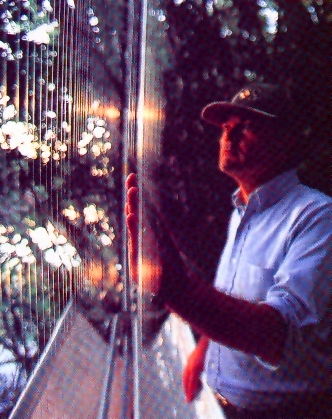 A "Harp Trap" is used to catch bats to study them. It is called
a harp trap because it resembles the musical instrument. The harp trap consists
of a frame and two sets of fine threads. The bat will see the first set of
strings and avoid them, however it will run into the second set and fall into a
bag suspended below the trap. The bat can then be safely removed for study. The
harp trap does not harm the bat. Harp traps are also used to catch birds for
study.
A "Harp Trap" is used to catch bats to study them. It is called
a harp trap because it resembles the musical instrument. The harp trap consists
of a frame and two sets of fine threads. The bat will see the first set of
strings and avoid them, however it will run into the second set and fall into a
bag suspended below the trap. The bat can then be safely removed for study. The
harp trap does not harm the bat. Harp traps are also used to catch birds for
study.
Site hosting sponsored by Invite Them Home SEO Services. Click to visit